2 Wire 4 20ma Wiring Diagram
This will help determine faults in the scale if any and increase stability of your readings. Better protection against wiring errors.

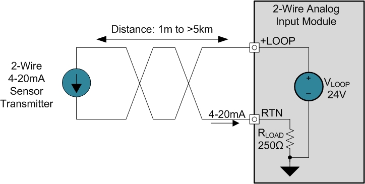
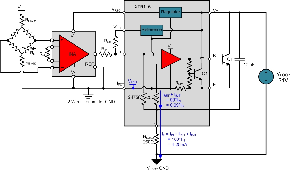
2Wire 420 mA Sensor Transmitters Understanding the 2wire Transmitter GND (Part 2
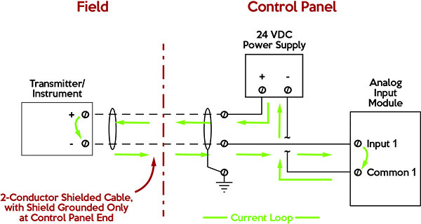
Connect the grounding wire (bare) to a suitable earth ground location in your building.

2 wire 4 20ma wiring diagram. 2, 3 and 4 wire loops in their vary basics. All devices in a 4 20 ma current loop need to be supplied power from somewhere in order to function. 3) connect the black wire to the input.
This question is answered best from the viewpoint of the user: It uses less wiring and connections than other signals, greatly reducing initial setup costs. It is assumed that the measurement device includes a sufficient load resistance for measuring a current loop.
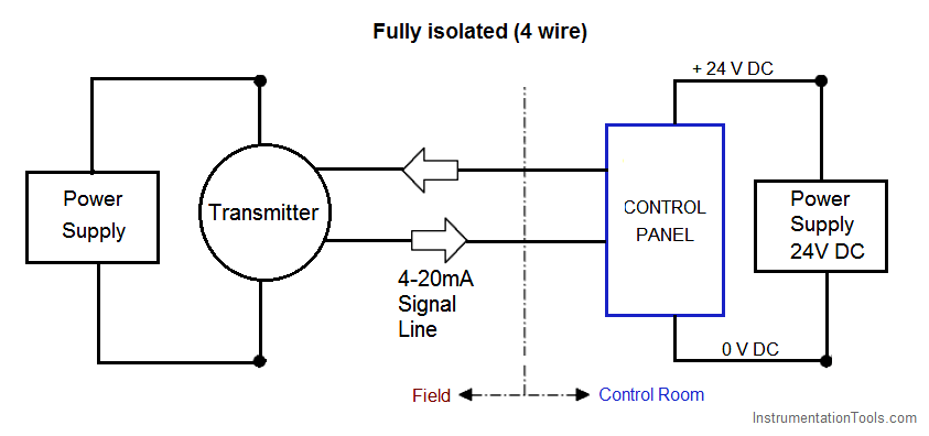
4 wire transducer to 4 wire module. Better for traveling long distances, as current does not degrade over long connections like voltage. Hello, i need wiring diagram to connect 2 wire and 4 wire transducer to analog input module for the following cases.
1) connect the red wire to a 24v dc outlet. 4 pin terminal rocker switch toggle switch wiring guide. A lot of loop setups will utilize an external power supply in order to power the devices which are attached to the current loop.
Connect the red wire to a 24v dc outlet. 2 wire transducer to 2 wire module. The diagram below below shows a simple wiring configuration for current loop pressure transmitter.
Ch2 (+) terminal with terminal (4) on. Es 335 wiring diagram humbucker pickup wire center •. A wiring diagram is a streamlined standard pictorial depiction of an electric circuit.
One of the world's most popular classic rock and blues pickups. Siemens strongly recommends that product updates are applied as soon as they are available and that the latest product versions are used. It is the simplest option to connect and configure.
2 wire transducer to 4 wire module. Better emc protection, since interferences can be filtered more easily. 2, 3 and 4 wire loops.
The 2 wire 3 wire and 4 wire types are often used to describe the method of connection of electronic transmitters. 2) connect the grounding wire (bare) to a suitable earth ground location in your building. 4 wire transducer to 2 wire module.
A wiring diagram is a simplified standard photographic representation of an electrical circuit. 2 wire pressure transducer wiring diagram 4 20ma transmitter circuit diagram awesome 3 wire pressure transducer wiring diagram. 2 wire pressure transducer wiring diagram 4 20ma transmitter circuit diagram awesome 3 wire pressure transducer wiring diagram.
White to black is just under 8k. 4 wire humbucker wiring diagram.

2Wire 420 mA Sensor Transmitters Understanding the 2wire Transmitter GND (Part 2

4 20ma Simulator Circuit Diagram Wiring View and Schematics Diagram

420 mA Transmitter Wiring Types 2Wire, 3Wire, 4Wire

Passive 420mA Current Loop Simulator Current Generator BRIGHTWIN

2wire 420mA Loop Simulator Signal Generator BRIGHTWIN
Industrial, 420 mA current loop, measuring circuits basics III. Industrial Circuits
2Wire 420 mA Sensor Transmitters Background and Compliance Voltage (Part 1) Precision Hub

2wire 420mA Loop Simulator Signal Generator BRIGHTWIN
4 to 20 mA Current Loop Output Signal SensorsONE

2wire 420mA Loop Simulator Signal Generator BRIGHTWIN

How to Implement a 420mA Transmitter wit Maxim Integrated

2Wire 420 mA Sensor Transmitters Background and Compliance Voltage (Part 1) Precision Hub

Basics of The 4 20mA Current Loop Learning Instrumentation And Control Engineering
Interfacing to twowire 420mA sensors

420 mA Transmitter Wiring Types 2Wire, 3Wire, 4Wire Transmitter, Wire, Current source

420 mA 2Wire Current Loop Sensor

Need more current than 4 mA in 4/20mA loop current Electrical Engineering Stack Exchange

2wire 420mA Loop Simulator Signal Generator BRIGHTWIN

4 20Ma Pressure Transducer Wiring Diagram / 2 Wire 4 20 Ma Sensor Transmitters Background And